|
 |
| Finned Tube |
| |
|
|
| |
|
|
| Finned Tube |
|
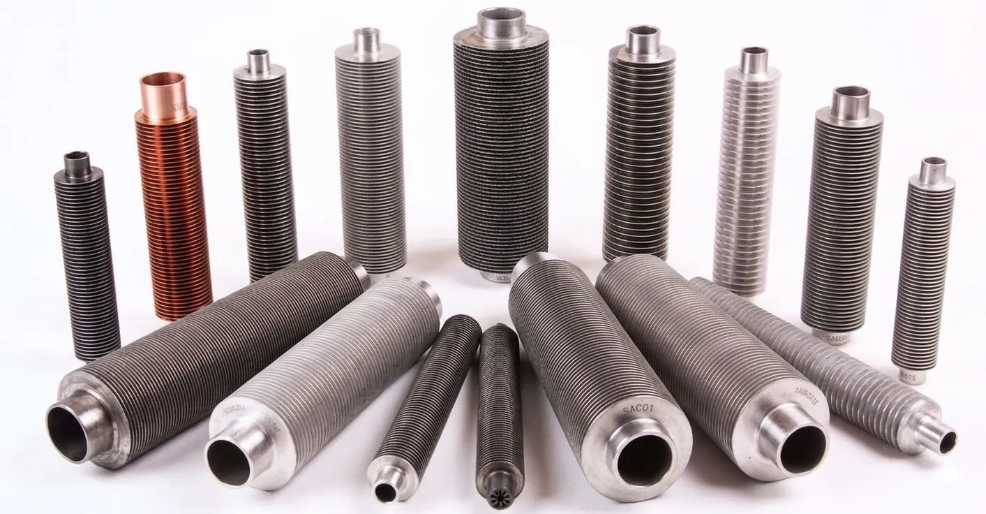
ASEA METAL supplies finned tubes in Korea for air coolers and heat exchangers. Choose fin type (L/LL/G/KL/extruded/studded) by duty and corrosion service, with base tube materials from carbon steel to stainless, duplex and alloys.
We manufacture finned tubes in Korea to improve heat transfer efficiency for process and power applications. Base tubes are supplied to project grade, commonly including ASTM A213 TP316L and ASTM A213 TP304L for corrosion service. Fin types (e.g., embedded G-type, L/LL/KL-type, laser-welded fin) are selected to match duty and operating temperature. We support inspection and release documentation including MTC (EN 10204 3.1 / 3.2) for export supply. As a Korean manufacturer, we can coordinate fin geometry and packing to protect surfaces in transit.
|
| ● Fin types |
L / LL / G (Embedded) / KL / Extruded / Serrated / Solid / Studded (by request) |
| ● Base tube |
Carbon steel, stainless, duplex, alloy steel (by service conditions) |
| ● Applications |
Air coolers, condensers/evaporators, boilers and gas turbine coolers |
| ● Inspection |
Dimensional / visual and project NDT options (PMI / Hydro / NDT) by request |
| ● Documents |
MTC (EN 10204 3.1 / 3.2) and traceability support |
|
Grades & equivalents
Confirm base tube material and fin material early. If you have an equivalent code (EN/JIS/ASTM), include it in your RFQ.
● Base tube |
Carbon (A179/A192)
SS 304/316L
Duplex 2205
Alloys (825/625)
|
● Fin material |
Aluminum
Copper
Stainless
Carbon steel
|
● Equivalents |
EN / JIS / ASTM equivalents can be reviewed upon request (share service temperature and corrosion conditions). |
Tip: For air coolers, specify fin type + fin geometry (height/thickness/pitch) and the maximum operating temperature.
|
Quality & inspection
● Dimensional / visual checks (fin geometry and tube straightness)
● Base tube inspection options (PMI / Hydro / NDT) by request
● MTC and traceability support for export projects
|
Packaging & delivery
● Protection for fins: separators / wrapping as required
● Bundles / wooden case for export packing (by request)
● Share destination port, Incoterms and target date in your RFQ
|
Request a quotation (RFQ)
For a quick quotation, ASEA METAL recommends including base tube OD/WT/length, fin type, fin height/thickness/pitch (TPi), material/grade, standard, quantity, inspection/documents (MTC/PMI/NDT) and delivery destination.
Contact / RFQ
|
Which fin types do you supply?
Typical fin types include L, LL, G (embedded), KL, extruded, serrated, solid and studded fin tubes depending on requirements.
Which base tube materials are available?
Carbon steel, stainless steel, duplex and alloy steel base tubes are available depending on order and project specification.
What should I include in an RFQ?
Please include base tube size, fin type and fin geometry (height/thickness/pitch), material/grade, standard, quantity, inspection/documents and destination.
Do you support MTC and inspection options?
Yes. MTC (EN 10204 3.1 / 3.2) and traceability support are available by request. Inspection scope (dimensional/visual, PMI, NDT options) can be aligned to project specification.
How do you pack finned tubes to protect the fins?
Fins can be protected with separators and wrapping as required. Bundles and export packing (including wooden cases/crates) can be arranged by request; share handling requirements and destination in the RFQ.
What details affect lead time and quotation?
Base tube size/grade, fin type, fin geometry (height/thickness/pitch), quantity, inspection scope and packing requirements all affect lead time. Please include target delivery date and destination port.
|
| Application |
| Condenser of Heat Exchanger , Condenser and evaporator of air-conditioner, Refrigerating machine, hot-water boiler, Gas turbine cooler, Air-fin |
| Type |
| L, LL , G(EMBEDDED), KL, EXTRUDED, STUDDED, SOLID, SERRATED, HIGH FIN , LOW FIN |
| Available Material |
| CARBON STEEL, STAINLESS STEEL, ALLOY STEEL, DUPLEX ETC |
| Technical Details per Type |
Fin tube classification
To make selection clearer, ASEA METAL groups finned tubes into three categories below. Existing fin type details are kept and shown under each category.
1) Air Fin (Wrap-on / mechanically bonded)
Typical: L / LL / KL / G (Embedded) / Extruded
Common fin materials: Aluminum, Copper (by duty)
2) Welded Fin (Welded / Spiral fin)
Typical: HF / HFW (High Frequency Welded), Studded
Fin material: carbon/stainless (project-dependent)
3) Integral Fin (Integral / Low Fin)
Fin is formed from the base tube material (low fin).
Used when cleanability and durability are important.
RFQ tip: include base tube OD/WT/length + fin type + fin geometry (height/thickness/pitch/TPi) + material/grade + quantity + inspection & documents (MTC/PMI/NDT).
|
1
Air Fin (Wrap-on / mechanically bonded)
Typical: L / LL / KL / G (Embedded) / Extruded — commonly with aluminum or copper fin material (by duty).
|
|
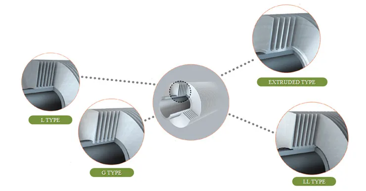
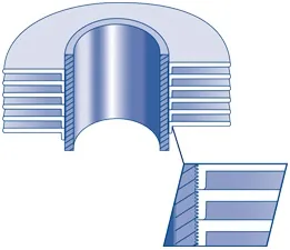
The strip material is subjected to controlled deformation under tension, giving the optimum contact pressure of the foot of the fin onto the base tube, thus maximizing the heat transfer properties. The foot of the fin considerably enhances the corrosion protection of the base tube.
Max. Temp: 150°C
Resistance: Atmos(Med), Mech(Low)
Materials: Alu, Copper
|
|
|
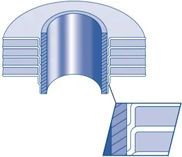
Manufactured the same way as the 'L' type, except the fin foot is overlapped to completely enclose the base tube, giving excellent corrosion resistance. Often used as an alternative to expensive extruded fins.
Max. Temp: 180°C
Resistance: Atmos(High), Mech(Low)
Materials: Alu, Copper
|
|
|
The base tube is knurled before the fin foot is applied. After application, the fin foot is knurled into the tube, enhancing the bond and improving heat transfer characteristics.
Max. Temp: 260°C
Resistance: Atmos(Med), Mech(Med)
Materials: Alu, Copper
|
|
|
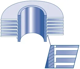
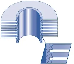
The fin strip is wound into a machined groove and securely locked into place by backfilling with base tube material. This ensures maximum heat transfer at high tube metal temperatures.
Max. Temp: 400°C
Resistance: Atmos(Low), Mech(Med)
Materials: Alu, Copper, Carbon Steel
|
|
|
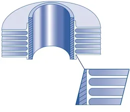
Formed from a bimetallic tube (aluminum outer/any material inner). The fin is rolled from the outside tube to give an integral fin with excellent longevity and outstanding corrosion protection.
Max. Temp: 285°C
Resistance: Atmos(High), Mech(High)
Materials: Aluminum
|
2
Welded Fin (Welded Fin / Spiral Fin)
Typical: HF / HFW (High Frequency Welded) and Studded fin tubes for robust fin attachment and higher temperature duties.
|
|
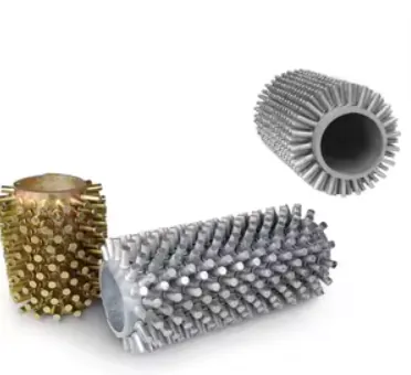
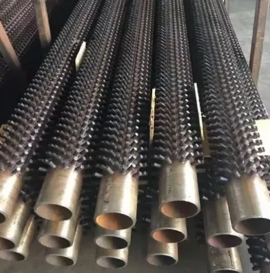
Carbon or low-alloy studs are resistance-welded to the base tube on a regular pitch. This pattern is widely used in high-temperature boiler and furnace convection sections, and in dusty or erosive gas streams where wrapped fins are less practical. Welded studs provide strong mechanical anchoring under thermal cycling.
Max. Temp: ~600°C (typ., grade-dependent)
Resistance: Atmos(Med), Mech(High)
Materials: Carbon / low-alloy steel
|
Studded Fin Tubes — design & quality
Key design & specification parameters
- Stud diameter / height: define projected area and tip clearance within the bundle.
- Stud pitch (circumferential & axial): sets density and pressure drop on the external gas side.
- Pattern: in-line vs staggered arrangement for fouling and mixing.
- Weld procedure: qualified parameters for stud material and tube grade.
- Tube OD / WT: pressure design and handling stiffness.
- Length / straightness: tube sheet fit and bundle assembly tolerances.
- End finishes: plain ends, bevels, grooves, end caps (as specified).
- Standards / documentation: aligned to customer drawing, code, and ITP (incl. MTC).
Quality & inspection (typical)
- Dimensional: stud height/pitch, tube OD/WT/length, straightness.
- Visual: stud alignment, weld appearance, missing studs, surface defects.
- Weld integrity: procedural checks / sampling per WPS and customer ITP.
- NDT (if required): base tube ET/UT, pressure test, PMI, hardness, etc. per PO/ITP.
- Traceability: heat/lot marking maintained through studding and packing.
|
High Frequency Finned Tubes (HF / HFW)
High-frequency resistance welding forms a strong, continuous bond between the fin and the base tube. This construction is widely used for
air-cooled heat exchangers and condenser/evaporator services where reliable heat transfer and fin integrity are required.
How HF finning works (overview)
- Continuous welding: the fin strip is formed and welded to the tube with high-frequency current.
- Controlled heat input: localized heating minimizes distortion while achieving stable fusion at the fin root.
- Repeatability: consistent parameters support uniform fin bond quality along the full tube length.
Why it matters (performance)
- High heat transfer stability: strong bond reduces contact resistance at the fin-to-tube interface.
- Mechanical integrity: suitable for air-side vibration and thermal cycling in air-coolers.
- Field-friendly: robust fin attachment helps reduce fin loosening during handling/transport.
Key design & specification parameters
- Fin pitch (fins/inch or mm): balances surface area vs. fouling/cleanability.
- Fin height: increases area; limited by bundle spacing and airflow pressure drop.
- Fin thickness: affects stiffness and corrosion allowance.
- Fin type: solid vs serrated (air-side turbulence).
- Tube OD/WT: governs pressure boundary and mechanical strength.
- Fin-to-tube weld profile: controlled geometry for consistent bond and appearance.
- Length / straightness: important for tube-to-tube sheet fit and bundle assembly.
- End finishes: plain ends, bevels, grooves, end caps (as specified).
Quality & inspection (typical)
- Dimensional: OD/WT/length, fin pitch/height, straightness, ovality.
- Visual: fin uniformity, fin root continuity, surface defects, handling marks.
- Bond integrity: checks per customer requirement (procedural checks / sample evaluation).
- NDT (if required): base tube ET/UT, pressure test, PMI, hardness, etc. per PO/ITP.
- Traceability: heat/lot marking maintained through finning and packing.
Corrosion & surface options
- Material selection: carbon steel, stainless, alloy, duplex for base tube; fin material selected by duty.
- Coatings (optional): painting/anti-corrosion coating on fins or tubes per project requirement.
- Service environment: consider marine/industrial atmosphere, sulfur/salt exposure, and cleaning chemistry.
Common fin types (HF welded)
- Solid fin: standard continuous fin for general duty.
- Serrated fin: improved turbulence/heat transfer; preferred for air-coolers.
- High fin / Low fin: selected by required surface area and pressure drop.
Aluminium fin tube options
- Extruded Al fin: excellent fin-to-tube contact and corrosion coverage.
- L / LL / KL: economical Al fin solutions for HVAC/coil-style duties.
- Selection: based on temperature, corrosion environment, and mechanical load on fins.
Typical specifications: fin pitch, fin height, fin thickness, base tube OD/WT/Length, and material (Carbon / Stainless / Alloy / Duplex).
Final scope follows PO/ITP.
Advantages
- Strong fin-to-tube bond for stable heat transfer.
- Good mechanical robustness for air-cooler bundles.
- Serrated fin option enhances performance on air side.
Selection notes
- Confirm corrosion environment and cleaning method.
- Decide fin pitch/height by fouling and pressure drop.
- Finalize with customer standard and project ITP.
|
High Frequency Finned Tubes (HF/HFW) — Quick Specification Guide
| Item |
Typical / Notes |
| Fin form |
Solid, Serrated, High fin, Low fin (per duty and pressure drop). |
| Base tube |
Carbon / Stainless / Alloy / Duplex. Common: ASTM A179/A192/A213/A269 (as specified). |
| Fin material |
Carbon steel / stainless (HF welded). Aluminium options available by extruded or L/LL/KL methods. |
| Operating temp. |
Defined by tube/fin material and service environment. Selection is finalized by customer spec and engineering review. |
| Applications |
Air-cooled heat exchangers, condensers, coolers, HVAC coils, refinery/petrochemical coolers, power/LNG auxiliary coolers. |
| Quality checks |
Dimensional, visual, fin bond integrity, marking/traceability; NDT and documentation per PO/ITP. |
3
Integral Fin (Integral / Low Fin)
Fins are formed from the base tube material (low fin) for durability and cleanability.
|
|
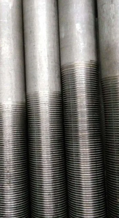
Integral (low) fins are formed directly from the base tube material, creating a durable, one-piece heat transfer surface with no separate fin strip to loosen.
This type is typically selected when cleanability, mechanical robustness and long-term stability are required.
Notes: Availability depends on OD/WT, fin geometry and base tube grade. Please share your drawing/spec in RFQ.
|
Integral Fin (Low Fin) Tubes
Low fins are mechanically formed from the tube wall itself, creating a single-material heat transfer surface without a separate fin strip. This can be preferred where handling durability and cleaning / maintenance are important.
How integral finning works (overview)
- One-piece construction: fins are formed from base tube material (no separate fin strip).
- Consistent surface: single alloy surface helps simplify material compatibility review.
- Fin geometry control: fin height/pitch are set by tooling and tube size.
Why it matters (selection)
- Cleanability: often selected when periodic cleaning is required.
- Mechanical robustness: no fin strip to unwrap or loosen during handling.
- Service match: used where “low fin” surface area is sufficient vs. high-fin air-cooler duties.
Key design & specification parameters
- Tube OD / WT: sets pressure design and available fin-forming range.
- Fin height / pitch: defines area increase and external-side pressure drop.
- Length / straightness: important for bundle assembly and tube sheet fit.
- Base tube material/grade: carbon / stainless / alloy / duplex as specified.
- Ends: plain / beveled / grooves / end caps (as specified).
- Documentation: MTC (EN 10204 3.1 / 3.2) and traceability by request.
Quality & inspection (typical)
- Dimensional: OD/WT/length, fin height/pitch, straightness.
- Visual: fin uniformity, surface defects and handling marks.
- NDT (if required): base tube ET/UT, pressure test, PMI, etc. per PO/ITP.
- Traceability: heat/lot marking maintained through production and packing.
RFQ checklist: base tube OD/WT/length, fin height/pitch, material/grade, quantity, inspection scope, documents (MTC), and destination.
|
|
| |
| Technical Highlights |
| |
| ● |
Heat transfer & fin selection: Fin type (L, LL, KL, G embedded, extruded, studded, serrated, etc.) is chosen from operating temperature, fouling tendency, and mechanical loads on fins. Higher metal temperatures and harsher duty favor embedded (G), extruded, or studded surfaces; L/LL types balance cost and corrosion coverage for air-cooled bundles and HVAC-style coils. |
| ● |
Base tube materials: Carbon steel, low-alloy, austenitic and duplex stainless, nickel alloys, and titanium-compatible combinations are supplied per your heat exchanger specification and compatibility with process fluid (sour service, chloride, ammonia). |
| ● |
Integral (low fin) tubes: Low fins are formed from the base tube material, providing a durable, single-material external surface. This option can be preferred where cleaning/maintenance and long-term mechanical stability are important. |
| ● |
Applications: Shell-and-tube and air-fin condensers and evaporators, process coolers, gas turbine intake/charge air coolers, refrigeration and LNG trains, power HRSG air heaters, and petrochemical heater convection sections - coordinate fin density, fin height, and tube layout with your thermal duty and allowable pressure drop. |
| ● |
Quality & documentation: Dimensional checks, fin-to-tube bond verification where applicable, and material traceability (MTC) aligned to ASTM/ASME or EN material orders; project-specific NDT or third-party inspection can be quoted with the inquiry. |
| ● |
HF/HFW fin bond integrity: High-frequency resistance welding provides a continuous fin-to-tube weld at the fin root, helping reduce thermal contact resistance and supporting stable performance under thermal cycling and air-side vibration (air coolers). |
| ● |
Serrated vs solid fin selection: Serrated fins increase air-side turbulence for higher heat transfer, while solid fins offer balanced performance. Choose fin type together with fin pitch/height considering allowable pressure drop, fouling tendency, and cleaning method. |
| ● |
Service environment & protection: For marine/industrial atmospheres, fin/tube material selection and optional anti-corrosion coating are important. Packaging (end caps, moisture control, VCI) helps maintain cleanliness and prevent damage during transport and storage. |
|
| |
Related topics & terms
Quick Reference: Finned Tube
ASEA METAL is a leading Korean manufacturer producing finned tubes for air coolers and heat exchangers (G/L/K).
Base tube: seamless (SMLS) ASTM A213 with MTC (EN 10204 3.1/3.2) by request.
Materials: 304/304L,316/316L(≈2.5%Mo),904/904L,Duplex S31803/S32205/S32750.
Procurement search terms: finned tube Korea factory, ASTM A213 TP316L base tube, Air Cooler Finned Tube, Bimetallic Finned Tube, MTC EN10204 3.1.
|
| |
|
| |
|
|